How To Make A Simple Robot
If you ever wanted to make a robot but didn't know where to start or have limited electrical/code knowledge here is a tutorial for you.
First gather up these supplies:
BOM
-Arduino mega
-Arduino motor shield
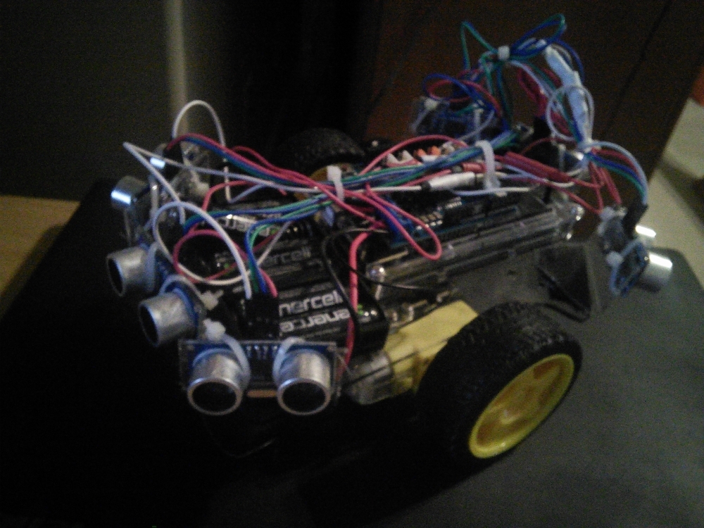
-Premade robot chassis of your choice I recommend one with two motorized wheels and one swivel wheels or two tank treads. I used this. Or if you want you can make your own chassis.
-Jumper wires
-Soldering supplies & shrink tube.
-Sensors of your choice. I used six proximity sensors. If you want you could use just one and have it rotate on a stepper motor.
-Power Supply: 9v battery and clip, 9V worth of AA, what ever you have available just be reasonable.
Connections
Just plug the motor shield into the arduino pins and hook the motor pins up to the terminal. Add a 9v battery to the power terminal if that's how you want to power it.
For the proximity sensors solder together some wires so that it goes from 5v on the arduino to the + pin on each of the proximity sensors. Do the same for ground.
The motor shield uses some of the pins by default so you will need to use different pins for the proximity sensors. So use whatever pins you want but keep pins A0, A1, 8, 9, 3, 11, 12, and 13 open for the motor shield.
Pin Functions
In the setup set the pin mode to be either input or output for the pins you use
Pins A0 and A1 are for current sensing, I didn't use these but you can if you want. (Good for preventing stalls) If you use these pins set them as an input.
Pins 8 and 9 are the brakes, make sure you disengage these in the setup by setting it as an output and to LOW. After that using these is optional. I make sure they are disengaged by including it in the motor control function
Pins 3 and 11 are for setting the speed 0-255. They use PWM set these pins as an output.
Pins 12 and 13 set the direction, these pins should also be set as an output.
For the proximity sensor the trigger pin is used to activate the sensor and should be set as an output and the echo pin to gather data and should be set as an input.
Code
Declare Variables
//SPEEDS
const int FAST = 200;
const int SLOW = 100;
//declare sensor pins
//sensor 1

const int pingPin1 = 22;
const int echoPin1 = 23;
//sensor2
const int pingPin2 = 24;
const int echoPin2 = 25;
//sensor 3
const int pingPin3 = 26;
const int echoPin3 = 27;
//sensor 4
const int pingPin4 = 28;
const int echoPin4 = 29;
//sensor 5
const int pingPin5 = 30;
const int echoPin5 = 31;
//sensor 6
const int pingPin6 = 32;
const int echoPin6 = 33;
//store distance read
long cm1, cm2, cm3, cm4, cm5, cm6;
//The direction of both motors and speed of each motor
long DIRECTION, speeda, speedb;
Setup: Set the pin mode of each pin.
void setup() {
//Setup Motor A
pinMode(12, OUTPUT);
pinMode(9, OUTPUT);
//Setup Motor B
pinMode(13, OUTPUT);
pinMode(8, OUTPUT);
//Setup ping pins
pinMode(pingPin1, OUTPUT);
pinMode(echoPin1, INPUT);
pinMode(pingPin2, OUTPUT);
pinMode(echoPin2, INPUT);
pinMode(pingPin3, OUTPUT);
pinMode(echoPin3, INPUT);
pinMode(pingPin4, OUTPUT);
pinMode(echoPin4, INPUT);
pinMode(pingPin5, OUTPUT);
pinMode(echoPin5, INPUT);
pinMode(pingPin6, OUTPUT);
pinMode(echoPin6, INPUT);
}
Now for the main loop
void loop()
{
//read sensors
ping();
//interpret data from sensors
logic();
//use data from sensors
motorcontrol();
}
Now we write the functions that we have called in the main loop.
Ping: Turn the trigger pin off, on, off. Delay 2 microseconds after the first off, then 5 microseconds after turning it on. Read the signal with pulseIn() and convert to cm using the conversion function we will write later.
long ping()
{
//variables
long duration;
//quick burst of electricity to the proximity sensor to activate it
digitalWrite(pingPin1, LOW);
delayMicroseconds(2);
digitalWrite(pingPin1, HIGH);
delayMicroseconds(5);
digitalWrite(pingPin1, LOW);
//reads signal that bounces back
duration= pulseIn(echoPin1,HIGH);
//converts duration to cm using function below
cm1 = microsecondsTocm(duration);
digitalWrite(pingPin2, LOW);
delayMicroseconds(2);
digitalWrite(pingPin2, HIGH);
delayMicroseconds(5);
digitalWrite(pingPin2, LOW);
//reads signal that bounces back
duration= pulseIn(echoPin2,HIGH);
//converts duration to cm using function below
cm2 = microsecondsTocm(duration);
Serial.print(cm2);
digitalWrite(pingPin3, LOW);
delayMicroseconds(2);
digitalWrite(pingPin3, HIGH);
delayMicroseconds(5);
digitalWrite(pingPin3, LOW);
//reads signal that bounces back
duration= pulseIn(echoPin3,HIGH);
//converts duration to cm using function below
cm3 = microsecondsTocm(duration);
digitalWrite(pingPin4, LOW);
delayMicroseconds(2);
digitalWrite(pingPin4, HIGH);
delayMicroseconds(5);
digitalWrite(pingPin4, LOW);
//reads signal that bounces back
duration= pulseIn(echoPin4,HIGH);
//converts duration to cm using function below
cm4 = microsecondsTocm(duration);
digitalWrite(pingPin5, LOW);
delayMicroseconds(2);
digitalWrite(pingPin5, HIGH);
delayMicroseconds(5);
digitalWrite(pingPin5, LOW);
//reads signal that bounces back
duration= pulseIn(echoPin5,HIGH);
//converts duration to cm using function below
cm5 = microsecondsTocm(duration);
digitalWrite(pingPin6, LOW);
delayMicroseconds(2);
digitalWrite(pingPin6, HIGH);
delayMicroseconds(5);
digitalWrite(pingPin6, LOW);
//reads signal that bounces back
duration= pulseIn(echoPin6,HIGH);
//converts duration to cm using function below
cm6 = microsecondsTocm(duration);
}
Convert to cm
//converts ping duration to cm
long microsecondsTocm(long microseconds)
{
return microseconds / 29 / 2;
}
Logic: This is what determines what the robot does based on the sensor input. This assumes we have 6 sensors: three in the back, three in the front. The middle sensors will be straight while the side sensors will be diagonal. When something triggers the center sensors it will reverse direction, if something is closer on one side sensor than the other, it will increase speed on one side and decrease speed on the other resulting in it turning away from the object it sensed. Please note that the placement of the sensors matters.
void logic()
{
/*
Direction Shifting:
The difference in distance between switching from forward to reverse (30) and
switching from reverse to forward (50) results in the robot having a tenancy
to go forward.
*/

//if it is going forward and gets close to something in front of it, switch to reverse
if (DIRECTION==LOW && cm1 > cm4 && cm4<30)
{
DIRECTION=HIGH;
}
//if it is in reverse and something is moderatly close switch to forward
if (DIRECTION==HIGH && cm4 > cm1 && cm1<30)
{
DIRECTION=LOW;
}
/*
Speed Control:
The speeds between the two wheels will always be different resulting in the robot having
a wavy motion as it moves thus "looking around". The difference in speeds also results
in the robot having a tenancy to move towards whichever side has the greatest amount of distance
thus moving away from walls and other objects. When in reverse the wheel speed difference is also
reversed.
*/
if (DIRECTION ==LOW)
{
if (cm5 > cm6)
{
speeda=FAST;
speedb=SLOW;
}
if (cm6 > cm5)
{
speeda=SLOW;
speedb=FAST;
}
}
if (DIRECTION ==HIGH)
{
if (cm2 > cm3)
{
speeda=FAST;
speedb=SLOW;
}
if (cm3 > cm2)
{
speeda=SLOW;
speedb=FAST;
}
}
}
Motor Control: Alright so now the robot knows what it want it wants to do and needs to tell the motor shield what to do.
//motor control
void motorcontrol()
{
digitalWrite(12, DIRECTION);
digitalWrite(9, LOW);
analogWrite(3, speeda);
digitalWrite(13, DIRECTION);
digitalWrite(8, LOW);
analogWrite(11, speedb);
}